For the last year or so, Yale’s DHLab has undertaken a series of experiments organized around analysis of visual culture. Some of those experiments have involved identifying similar images and visualizing patterns uncovered in this process. In this post, I wanted to discuss how we used the amazing Three.js library to build a WebGL-powered visualization that can display tens of thousands of images in an interactive 3D environment [click to enter]:
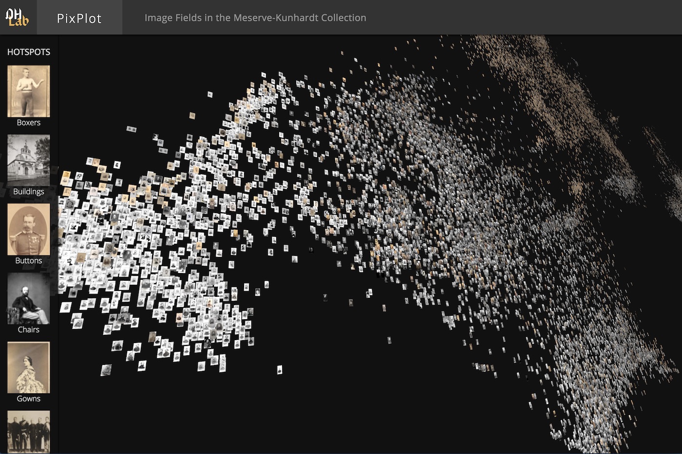
If you’re interested in creating something similar, feel free to check out the full code.
Getting Started with Three.js
Three.js is a JavaScript library that generates lower-level code for WebGL, the standard API for 3D rendering in a web browser. Using Three.js, one can build complex 3D environments that would take much more code to build in raw WebGL. For a quick sample of the projects others have built with the library, check out the Three.js homepage.
To get started with Three.js, one needs to provide a bit of boilerplate code with the three essential elements of a Three.js page:
scene: The scene contains all objects to be rendered:
// Create the scene and a camera to view it
var scene = new THREE.Scene();camera: The camera determines the position from which viewers see the scene:
// Specify the portion of the scene visiable at any time (in degrees)
var fieldOfView = 75;

// Specify the camera's aspect ratio
var aspectRatio = window.innerWidth / window.innerHeight;

// Specify the near and far clipping planes. Only objects
// between those planes will be rendered in the scene
// (these values help control the number of items rendered
// at any given time)
var nearPlane = 0.1;
var farPlane = 1000;

// Use the values specified above to create a camera
var camera = new THREE.PerspectiveCamera(
  fieldOfView, aspectRatio, nearPlane, farPlane
);

// Finally, set the camera's position in the z-dimension
camera.position.z = 5;renderer: The renderer renders the scene to a canvas element on an HTML page:
// Create the canvas with a renderer and tell the
// renderer to clean up jagged aliased lines
var renderer = new THREE.WebGLRenderer({antialias: true});

// Specify the size of the canvas
renderer.setSize( window.innerWidth, window.innerHeight );

// Add the canvas to the DOM
document.body.appendChild( renderer.domElement );
The code above creates the scene, adds a camera, and renders the canvas to the DOM. Now all we need to do is add some objects to the scene.
Each item rendered in a Three.js scene has a geometry and a material. Geometries use vertices (points) and faces (polygons described by vertices) to define the shape of an object, and materials use textures and colors to define the appearance of that shape. A geometry and a material can be combined into a mesh, which is a fully composed object ready to be added to a scene.
The example below uses the high-level BoxGeometry, which comes with pre-built vertices and faces:
// Create a cube with width, height, and depth set to 1
var geometry = new THREE.BoxGeometry( 1, 1, 1 );

// Use a simple material with a specified hex color
var material = new THREE.MeshBasicMaterial({ color: 0xffff00 });

// Combine the geometry and material into a mesh
var cube = new THREE.Mesh( geometry, material );

// Add the mesh to the scene
scene.add( cube );
Finally, to render the scene on the page, one must call the render() method, passing in the scene and the camera as arguments:
renderer.render( scene, camera );Combining the snippets above gives the following result:
See the Pen The Simplest Three.js Scene by Douglas Duhaime (@duhaime) on CodePen.
This is great, but the scene is static. To add some animation to the scene, one can periodically update the cube’s rotation property, then rerender the scene. To do so, one can replace the renderer.render() line above with a render loop that calls itself recursively. Here is a standard render loop in Three.js:
function animate() {
  requestAnimationFrame( animate );
  renderer.render( scene, camera );

  // Rotate the object a bit each animation frame
  cube.rotation.y += 0.01;
  cube.rotation.z += 0.01;
}
animate();
Adding this block at the bottom of the script makes the cube slowly rotate:
See the Pen Animating the Cube by Douglas Duhaime (@duhaime) on CodePen.
Adding lights to the scene can make it easier to differentiate the faces of the cube. To add lights to the scene above, we’ll first want to change the cube’s material, because as the documentation says the MeshBasicMaterial is not affected by lights. Let’s replace the material defined above with a MeshPhongMaterial:
var material = new THREE.MeshPhongMaterial({color: 0xffff00})Next let’s point a light at the cube so that different faces of the cube catch different amounts of light:
// Add a point light with #fff color, .7 intensity, and 0 distance
var light = new THREE.PointLight(0xffffff, .7, 0);

// Specify the light's position in the x, y, and z dimensions
light.position.set(1, 1, 100);

// Add the light to the scene
scene.add(light)
Voila!
See the Pen Lighting the Cube by Douglas Duhaime (@duhaime) on CodePen.
Adding Images to a Scene
The snippets above give a quick overview of the core elements of a Three.js scene. The following section will build upon those ideas to create a TSNE map of images.
To build an image viewer, we’ll need to load some image files into some Three.js materials. We can do so by using the TextureLoader:
// Create a texture loader so we can load the image file
var loader = new THREE.TextureLoader();

// Specify the path to an image
var url = 'https://s3.amazonaws.com/duhaime/blog/tsne-webgl/assets/cat.jpg';

// Load an image file into a MeshLambert material
var material = new THREE.MeshLambertMaterial({
  map: loader.load(url)
});
Now that the material is ready, the remaining steps are to generate a geometry from the image, combine the material and geoemtry into a mesh, and add the mesh to the scene, just like the cube example above. Because images are two-dimensional planes, we can use a simple PlaneGeometry for this object’s geometry:
// create a plane geometry for the image with a width of 10
// and a height that preserves the image's aspect ratio
var geometry = new THREE.PlaneGeometry(10, 10*.75);

// combine the image geometry and material into a mesh
var mesh = new THREE.Mesh(geometry, material);

// set the position of the image mesh in the x,y,z dimensions
mesh.position.set(0,0,0)

// add the image to the scene
scene.add(mesh);
The image will now appear in the scene:
See the Pen Adding an Image to a Three.js Scene by Douglas Duhaime (@duhaime) on CodePen.
It’s worth noting that one can swap out the PlanarGeometry for other geometries and Three.js will automatically wrap the material over the new geometry. The example below, for instance, swaps the PlanarGeometry for a more interesting Icosahedron geometry, and rotates the icosahedron inside the render loop:
// use an icosahedron geometry instead of the planar geometry
var geometry = new THREE.IcosahedronGeometry();

// spin the icosahedron each animation frame
function animate() {
requestAnimationFrame( animate );
  renderer.render( scene, camera );
  mesh.rotation.x += 0.01;
  mesh.rotation.y += 0.01;
  mesh.rotation.z += 0.01;
}
animate();
This produces a strange looking cat indeed:
See the Pen Icosahedron Cat by Douglas Duhaime (@duhaime) on CodePen.
Building Custom Geometries
The examples above use a few different geometries built into Three.js. Those geometries are based on the fundamental THREE.Geometry class, which is a primitive geometry one can use to create custom geometries. THREE.Geometry is lower-level than the prebuilt geometries used above, but it gives performance gains that make it worth the effort.
Let’s create a custom geometry by calling the THREE.Geometry constructor, which takes no arguments:
var geometry = new THREE.Geometry();This geometry object doesn’t do much yet, because it doesn’t have any vertices with which to ariculate a shape. Let’s add four vertices to the geometry, one for each corner of the image. Each vertex takes three arguments, which define the vertex’s x, y, and z positions respectively:
// identify the image width and height
var imageSize = {width: 10, height: 7.5};

// identify the x, y, z coords where the image should be placed
// inside the scene
var coords = {x: -5, y: -3.75, z: 0};

// add one vertex for each image corner in this order:
// lower left, lower right, upper right, upper left
geometry.vertices.push(
  new THREE.Vector3(
    coords.x,
    coords.y,
    coords.z
  ),
  new THREE.Vector3(
    coords.x+imageSize.width,
    coords.y,
    coords.z
  ),
  new THREE.Vector3(
    coords.x+imageSize.width,
    coords.y+imageSize.height,
    coords.z
  ),
  new THREE.Vector3(
    coords.x,
    coords.y+imageSize.height,
    coords.z
  )
);
Now that the vertices are in place, we need to add some faces to the geometry. The code below will model an image as two triangle faces, as triangles are performant primitives in the WebGL world. The first triangle will combine the lower-left, lower-right, and upper-right vertices of the image, and the second will triangulate the lower-left, upper-right, and upper-left vertices of the image:
// add the first face (the lower-right triangle)
var faceOne = new THREE.Face3(
  geometry.vertices.length-4,
  geometry.vertices.length-3,
  geometry.vertices.length-2
)

// add the second face (the upper-left triangle)
var faceTwo = new THREE.Face3(
  geometry.vertices.length-4,
  geometry.vertices.length-2,
  geometry.vertices.length-1
)

// add those faces to the geometry
geometry.faces.push(faceOne, faceTwo);
Awesome, we now have a geometry with four vertices that describe the corners of the image, and two faces that describe the lower-right and upper-left-hand triangles of the image. The next step is to describe which portions of the cat image should appear in each of the faces of the geometry. To do so, one must add some faceVertexUvs to the geometry, as faceVertexUvs indicate which portions of a texture should appear in which portions of a geometry.
FaceVertexUvs represent a texture as a two-dimensional plane that stretches from 0 to 1 in the x dimension and 0 to 1 in the y dimension. Within this coordinate system, 0,0 represents the bottom-left-most region of the texture, and 1,1 represents the top-right-most region of the texture. Given this coordinate system, we can map the lower-right triangle of the image to the first face created above, and we can map the upper-left triangle of the image to the second face created above:
// map the region of the image described by the lower-left,
// lower-right, and upper-right vertices to the first face
// of the geometry
geometry.faceVertexUvs[0].push([
  new THREE.Vector2(0,0),
  new THREE.Vector2(1,0),
  new THREE.Vector2(1,1)
]);

// map the region of the image described by the lower-left,
// upper-right, and upper-left vertices to the second face
// of the geometry
geometry.faceVertexUvs[0].push([
  new THREE.Vector2(0,0),
  new THREE.Vector2(1,1),
  new THREE.Vector2(0,1)
]);
With the uv coordinates in place, one can render the custom geometry within the scene just as above:
See the Pen Building Custon Geometries by Douglas Duhaime (@duhaime) on CodePen.
This may seem like a lot of work for the same result we achieve with a one-line PlanarGeometry declaration above. If a scene only required one image and nothing else, one could certainly use the PlanarGeometry and call it a day.
However, each mesh added to a Three.js scene necessitates an additional “draw call”, and each draw call requires the browser agent’s CPU to send all mesh related data to the browser agent’s GPU. These draw calls happen for each mesh during each animation frame, so if a scene is running at 60 frames per second, each mesh in that scene will require the transportation of data from the CPU to the GPU sixty times per second. In short, more draw calls means more work for the host device, so reducing the number of draw calls is essential if you want to keep animations smooth and close to sixty frames per second.
The upshot of all this is that a scene with tens of thousands of PlanarGeometry meshes will grind a browser to a halt. To render lots of images in a scene, it’s much more performant to use a custom geometry like the one above, and to push lots of vertices, faces, and vertex uvs into that geometry. We’ll explore this idea more below.
Displaying multiple images
Given the remarks above let’s next build a single geometry that contains multiple images. To do so, we’ll need to load a number of images into the page in which the scene is running. One way to accomplish this task is to pass a series of urls to the texture loader and load each image individually. The trouble with this approach is it requires one new HTTP request for each image to be loaded, and there are upper bounds to the number of HTTP requests a given browser can make to a given domain at a time.
A common solution to this problem is to load an “image atlas”, or montage of small images combined into a single larger image:
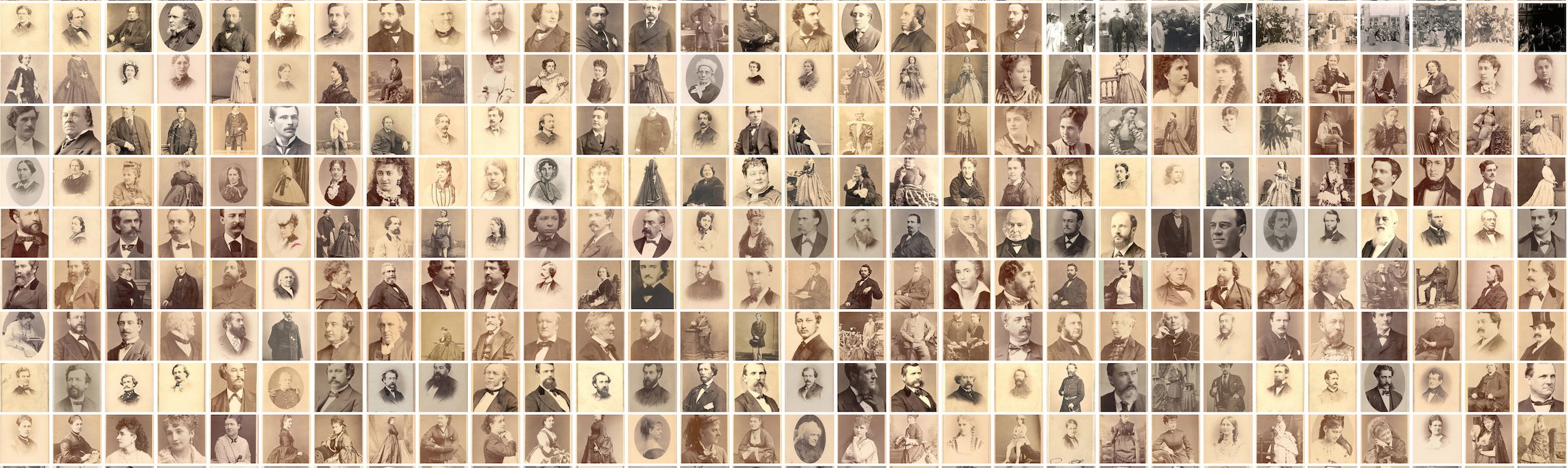
One can then use the montage the way that performance-minded sites like Google use spritesheets. If you have ImageMagick installed, you can create one of these montages with the montage command:
# download directory of images
wget https://s3.amazonaws.com/duhaime/blog/tsne-webgl/data/100-imgs.tar.gz
tar -zxf 100-imgs.tar.gz

# create a file that lists all files to be include in the montage
ls 100-imgs/* > images_to_montage.txt

# create single montage image from images in a directory
montage `cat images_to_montage.txt` -geometry +0+0 -background none -tile 10x 100-img-atlas.jpg
The last command will create an image atlas with 10 images per column and no padding between the images in the atlas. The sample directory 100-imgs.tar.gz contains 100 images, and the -tile argument in the montage command indicates ouput atlas should have 10 columns, so the command above will generate a 10x10 grid of size 1280px by 1280px.
Let’s load the image atlas into a Three.js scene:
// Create a texture loader so we can load the image file
var loader = new THREE.TextureLoader();

// Load an image file into a custom material
var material = new THREE.MeshBasicMaterial({
  map: loader.load('https://s3.amazonaws.com/duhaime/blog/tsne-webgl/data/100-img-atlas.jpg')
});
Once the image atlas is loaded in, we’ll want to create some helper objects that identify the size of the atlas and its sub images. Those helper objects can then be used to calculate the vertex uvs of each face in a geometry:
// Identify the subimage size in px
var image = {width: 128, height: 128};

// Identify the total number of cols & rows in the image atlas
var atlas = {width: 1280, height: 1280, cols: 10, rows: 10};
The custom geometry example above used four vertices and two faces to render a single image. To represent all 100 images from the image atlas, we can create four vertices and two faces for each of the 100 images to be displayed. Then we can associate the proper region of the image atlas material with each of the geometry’s 200 faces:
// Create a helper function that returns an int {-700,700}.
// We'll use this function to set each subimage's x and
// y coordinate positions
function getRandomInt() {
  var val = Math.random() * 700;
  return Math.random() > 0.5
    ? -val
    : val;
}

// Create the empty geometry
var geometry = new THREE.Geometry();

// For each of the 100 subimages in the montage, add four
// vertices (one for each corner), in the following order:
// lower left, lower right, upper right, upper left
for (var i=0; i<100; i++) {

  // Create x, y, z coords for this subimage
  var coords = {
    x: getRandomInt(),
    y: getRandomInt(),
    z: -400
  };

  geometry.vertices.push(
    new THREE.Vector3(
      coords.x,
      coords.y,
      coords.z
    ),
    new THREE.Vector3(
      coords.x + image.width,
      coords.y,
      coords.z
    ),
    new THREE.Vector3(
      coords.x + image.width,
      coords.y + image.height,
      coords.z
    ),
    new THREE.Vector3(
      coords.x,
      coords.y + image.height,
      coords.z
    )
  );

  // Add the first face (the lower-right triangle)
  var faceOne = new THREE.Face3(
    geometry.vertices.length-4,
    geometry.vertices.length-3,
    geometry.vertices.length-2
  )

  // Add the second face (the upper-left triangle)
  var faceTwo = new THREE.Face3(
    geometry.vertices.length-4,
    geometry.vertices.length-2,
    geometry.vertices.length-1
  )

  // Add those faces to the geometry
  geometry.faces.push(faceOne, faceTwo);

  // Identify this subimage's offset in the x dimension
  // An xOffset of 0 means the subimage starts flush with
  // the left-hand edge of the atlas
  var xOffset = (i % 10) * (image.width / atlas.width);

  // Identify the subimage's offset in the y dimension
  // A yOffset of 0 means the subimage starts flush with
  // the top edge of the atlas
  var yOffset = Math.floor(i/10) * (image.height / atlas.height);

  // Use the xOffset and yOffset (and the knowledge that
  // each row and column contains only 10 images) to specify
  // the regions of the current image
  geometry.faceVertexUvs[0].push([
    new THREE.Vector2(xOffset, yOffset),
    new THREE.Vector2(xOffset+.1, yOffset),
    new THREE.Vector2(xOffset+.1, yOffset+.1)
  ]);

  // Map the region of the image described by the lower-left,
  // upper-right, and upper-left vertices to `faceTwo`
  geometry.faceVertexUvs[0].push([
    new THREE.Vector2(xOffset, yOffset),
    new THREE.Vector2(xOffset+.1, yOffset+.1),
    new THREE.Vector2(xOffset, yOffset+.1)
  ]);
}

// Combine the image geometry and material into a mesh
var mesh = new THREE.Mesh(geometry, material);

// Set the position of the image mesh in the x,y,z dimensions
mesh.position.set(0,0,0)

// Add the image to the scene
scene.add(mesh);
Rendering that scene produces a crazy little scatterplot of images:
See the Pen Loading Multiple Images by Douglas Duhaime (@duhaime) on CodePen.
Here we represent one hundred images with just a single mesh! This is much better than giving each image its own mesh, as it reduces the number of required draw calls by two orders of magnitude. It’s worth noting, however, that eventually one does need to create additional meshes. A number of graphics devices can only handle 2^16 vertices in a single mesh, so if you need your scene to run on a wide range of devices it’s best to ensure each mesh contains 65,536 or fewer vertices.
Using Multiple Atlas Files
Having discovered how to visualize multiple images with a single mesh, we can now scale up the image collection size dramatically.
One way to crank up the number of visualized images is to squeeze more images into the image atlas. As it turns out, however, the largest texture size supported by many devices is 2048 x 2048px, so the code below will stick to atlas files of that size.
For the examples below, I took roughly 20,480 images, resized each to 32px thumbs, then used the montage technique discuss above to build the following atlas files: 1, 2, 3, 4, 5. Once those atlas files are loaded onto a static file server, one can load each atlas into a scene with a simple loop:
// Create a store that maps each atlas file's index position
// to its material
var materials = {};

// Create a texture loader so we can load the image file
var loader = new THREE.TextureLoader();

for (var i=0; i<5; i++) {
  var url = 'https://s3.amazonaws.com/duhaime/blog/tsne-webgl/data/atlas_files/32px/atlas-' + i + '.jpg';
  loader.load(url, handleTexture.bind(null, i));
}

// Callback function that adds the texture to the list of textures
// and calls the geometry builder if all textures have loaded
function handleTexture(idx, texture) {
  materials[idx] = new THREE.MeshBasicMaterial({ map: texture })
  if (Object.keys(materials).length === 5) {
    document.querySelector('#loading').style.display = 'none';
    buildGeometry();
  }
}
The buildGeometry function will then create the vertices and faces for the 20,000 images within the atlas files. Once those are set, one can pump those geometries into some meshes and add the meshes to the scene (click the Codepen link for the full code update):
See the Pen Loading Multiple Atlas Files by Douglas Duhaime (@duhaime) on CodePen.
Positioning Images with TSNE Coordinates
So far we’ve used random coordinates to place images within a scene. Let’s now position images near other similar-looking images. To do so, we’ll create vectorized representations of each image, project those vectors down into a 2D embedding, then use each image’s position in the 2D coordinate space to position the image in the Three.js scene.
Generating TSNE Coordinates
First things first, let’s create a vector representation of each image. If you have tensorflow installed, you can create vectorized representations of each image in 100-imgs by running:
# download a script that generates vectorized representations of images
wget https://gist.githubusercontent.com/duhaime/2a71921c9f4655c96857dbb6b6ed9bd6/raw/0e72c48e698395265d029fabad0e6ab1f3961b26/classify_images.py

# install a dependency for process management
pip install psutil

# run the script on a glob of images
python classify_images.py '100-imgs/*'
This script will generate one image vector for each image in 100-imgs/. We can then run the following script to create a 2D TSNE projection of those image vectors:
# create_tsne_projection.py
from sklearn.manifold import TSNE
import numpy as np
import glob, json, os

# create datastores
image_vectors = []
chart_data = []
maximum_imgs = 20480

# build a list of image vectors
vector_files = glob.glob('image_vectors/*.npz')[:maximum_imgs]
for c, i in enumerate(vector_files):
  image_vectors.append(np.loadtxt(i))
  print(' * loaded', c+1, 'of', len(vector_files), 'image vectors')

# build the tsne model on the image vectors
model = TSNE(n_components=2, random_state=0)
np.set_printoptions(suppress=True)
fit_model = model.fit_transform( np.array(image_vectors) )

# store the coordinates of each image in the chart data
for c, i in enumerate(fit_model):
  chart_data.append({
    'x': float(i[0]),
    'y': float(i[1]),
    'idx': c
  })

with open('image_tsne_projections.json', 'w') as out:
  json.dump(chart_data, out)
Running that TSNE script on your image vectors will generate a JSON file in which each input image is mapped to x and y coordinate values:
[
  { 'x': 95.027, 'y': 11.80  },
  { 'x': 98.54,  'y': -30.42 }, ...
]
Positioning Images in a Three.js Scene
Given the JSON file with those TSNE coordinates, all we need to do is iterate over each item in the JSON file and position the image in that index position accordingly.
To load a JSON file using the Three.js library, we can use a FileLoader:
// Create a store for image position information
var imagePositions = null;

var loader = new THREE.FileLoader();
loader.load('https://s3.amazonaws.com/duhaime/blog/tsne-webgl/data/image_tsne_projections.json', function(data) {
  imagePositions = JSON.parse(data);
  // Build the geometries if all atlas files are loaded
  conditionallyBuildGeometries()
})
We can then use the index position of each item in that JSON file to identify the appropriate atlas file and x, y offsets for a given image. To do so, we’ll need to store each material by its index position:
// Create a texture loader so we can load the image file
var loader = new THREE.TextureLoader();
for (var i=0; i<5; i++) {
  var url = 'https://s3.amazonaws.com/duhaime/blog/tsne-webgl/data/';
  url += 'atlas_files/32px/atlas-' + i + '.jpg';
  // Pass the texture index position to the callback function
  loader.load(url, handleTexture.bind(null, i));
}

// Callback function that adds the texture to the list of textures
// and calls the geometry builder if all textures have loaded
function handleTexture(idx, texture) {
  materials[idx] = new THREE.MeshBasicMaterial({ map: texture })
  conditionallyBuildGeometries()
}

// If the textures and the mapping from image idx to positional information
// are all loaded, create the geometries
function conditionallyBuildGeometries() {
  if (Object.keys(materials).length === 5 && imagePositions) {
    document.querySelector('#loading').style.display = 'none';
    buildGeometry();
  }
}
Then buildGeometry() can then pass the index position of each atlas i and the index position of each image within a given atlas j to getCoords(), a function that returns the given image’s x and y coordinates:
// Identify the total number of cols & rows in the image atlas
var atlas = {width: 2048, height: 2048, cols: 64, rows: 64};

// Create a new mesh for each texture
function buildGeometry() {
  for (var i=0; i<5; i++) {
    // Create one new geometry per atlas
    var geometry = new THREE.Geometry();
    for (var j=0; j< atlas.cols*atlas.rows; j++) {
      var coords = getCoords(i, j);
      geometry = updateVertices(geometry, coords)
      geometry = updateFaces(geometry)
      geometry = updateFaceVertexUvs(geometry, j)
    }
    buildMesh(geometry, materials[i])
  }
}

// Get the x, y, z coords for the subimage in index position j
// of atlas in index position i
function getCoords(i, j) {
  var idx = (i * atlas.rows * atlas.cols) + j;
  var coords = imagePositions[idx];
  coords.x *= 1200;
  coords.y *= 600;
  coords.z = (-200 + j/100);
  return coords;
}
Adding Controls
In addition to setting the image positions, we can add some controls to the scene that allow users to zoom in or out. An easy way to do so is to add the pre-packaged trackball controls as an additional JavaScript dependency. Then we can call the control’s constructor and update the controls both on window resize events and inside the main render loop to keep the controls up to date with the application state:
/**
* Add Controls
**/

var controls = new THREE.TrackballControls(camera, renderer.domElement);

/**
* Handle window resizes
**/

window.addEventListener('resize', function() {
  camera.aspect = window.innerWidth / window.innerHeight;
  camera.updateProjectionMatrix();
  renderer.setSize( window.innerWidth, window.innerHeight );
  controls.handleResize();
});

/**
* Render!
**/

// The main animation function
function animate() {
requestAnimationFrame( animate );
  renderer.render( scene, camera );
  controls.update();
}
animate();
The result is an interactive visualization of the images in a 2D TSNE projection:
See the Pen Three.js - Positioning Images with TSNE Coordinates by Douglas Duhaime (@duhaime) on CodePen.
Getting Fancy
We’ve now achieved a basic TSNE map with Three.js, but there’s much more that could be done to improve a user’s experience of the visualization. In particular, within the extant plot:
-
* Users get no indication of load progress
* Users can't see details within the small images
* Users have no guide through the visualization
To see how our team resolved those challenges, feel free to visit the live site or the GitHub repository with the full source code. Otherwise, if you’re working on something similar, feel free to send me a note or a comment below–I’d love to see what you’re building.
I want to thank Cyril Diagne, a lead developer on the spectacular Google Arts Experiments TSNE viewer, for generously sharings ideas and optimization techniques that we used to build our own TSNE viewer.